
Choosing the right power infrastructure can determine whether a project operates smoothly or struggles with repeated interruptions. A Substation With Transformer combines voltage transformation, switching, protection, and distribution within one coordinated installation. This arrangement can simplify planning for industrial sites, commercial facilities, renewable energy plants, and remote infrastructure.
In practical projects, engineers examine load demand, fault levels, expansion plans, site conditions, and maintenance access. A properly selected transformer can reduce transmission losses and deliver usable voltage to downstream equipment. Integrated protection systems also help isolate faults before they damage valuable machinery. Clearances matter. So does ventilation.
Experienced electrical teams usually review transformer capacity, impedance, cooling method, enclosure design, and future operating conditions. They may compare oil-immersed and dry-type transformers according to fire considerations, environmental conditions, and indoor requirements. Applicable IEC, IEEE, and local electrical standards should guide the design and testing process. Independent inspection and documented factory testing add confidence before installation.
No design is flawless. An oversized transformer may increase initial costs and create inefficient low-load operation. An undersized unit can overheat when production expands. This is where careful engineering judgment becomes essential. Site surveys, realistic load measurements, and maintenance feedback often reveal issues that drawings miss. Reliable suppliers should provide verified specifications, test records, warranty terms, and responsive technical support. When these details receive proper attention, a Substation With Transformer can offer safer distribution, controlled operating costs, and practical room for future growth.
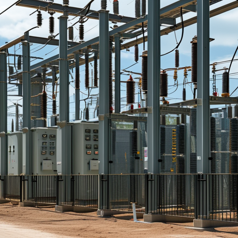
A substation with transformer is a controlled electrical facility that changes voltage between transmission, distribution, and industrial systems. It combines transformers with switchgear, protection relays, busbars, metering equipment, and grounding networks. The transformer performs the central task. It raises or lowers voltage while keeping electrical power within usable limits.
In practical projects, the substation receives electricity at a higher voltage and delivers safer, suitable voltage to buildings, factories, or local networks. Protective devices detect faults and disconnect damaged sections quickly. Grounding provides a planned path for fault current, helping protect workers, equipment, and nearby structures. Clearances, ventilation, oil containment, fire protection, and access routes also require careful engineering. Small details matter here.
Site conditions influence every decision. Soil resistance, rainfall, temperature, load growth, and maintenance access can change the design. An apparently correct capacity may become inadequate after expansion. That assumption deserves review. Engineers normally confirm transformer ratings through load studies, short-circuit calculations, and relevant electrical standards. Factory testing and commissioning checks add valuable evidence, but field conditions can still reveal unexpected issues. Reliable operation depends on accurate data, documented inspections, and trained personnel. Some projects also benefit from remote monitoring, although communication failures must be considered.
A transformer substation connects generation, transmission, and distribution networks. Its central transformer changes voltage through electromagnetic induction. High-voltage electricity enters the primary winding, while the secondary winding delivers a safer, usable voltage. Step-down transformers serve factories, buildings, and local distribution lines. Step-up transformers support long-distance transmission by reducing current and resistive losses.
The process is controlled, not passive. Incoming power passes through circuit breakers, isolators, and surge arresters before reaching the transformer. Relays monitor overcurrent, short circuits, oil temperature, and winding temperature. If a fault appears, the breaker disconnects the affected section within milliseconds. Cooling fins, radiators, or fans remove heat from the core and windings. Supervisory systems record loading and alarms, helping operators identify abnormal behavior before failure. Small details matter.
The International Energy Agency reported in Electricity Grids and Secure Energy Transitions that annual grid investment must rise above 600 billion dollars by 2030. This pressure makes transformer substations important for capacity expansion and resilience. However, selecting one only by rated power can be misleading. Load diversity, harmonic distortion, ambient temperature, fire protection, maintenance access, and future demand also influence performance. A 10 MVA transformer may appear sufficient today, yet continuous high loading can shorten insulation life. That assumption can fail. Engineers should verify site measurements, fault levels, protection coordination, and applicable IEC 60076 requirements before final design.
Why Choose a Substation With Transformer for Your Project?
A transformer substation addresses a project’s most basic electrical need: safe voltage conversion. It receives power at transmission or medium voltage and delivers usable voltage to buildings, factories, or infrastructure. The IEA’s Electricity 2024 report forecasts global electricity demand to grow by an average of 3.4% annually through 2026. That growth increases pressure on existing networks. A dedicated substation can support expanding loads, reduce voltage drops, and create clearer protection zones. It also allows engineers to isolate faults without shutting down every connected facility. This matters for hospitals, data centers, manufacturing sites, and large commercial developments.
Tips: Define the maximum demand early. Include motor starting current, future expansion, and seasonal peaks. Select transformer capacity with measured data, not optimistic estimates. Review short-circuit levels and cooling conditions against IEC 60076 requirements. Keep maintenance access visible on the layout. Small details become expensive later.
Reliability is another project need. NERC’s 2024 Long-Term Reliability Assessment highlights growing demand and resource adequacy concerns across North American power systems. A substation with properly coordinated transformers, breakers, relays, and backup arrangements can improve operational resilience. Renewable generation may also require voltage regulation and bidirectional power-flow planning. However, larger equipment is not automatically better. Oversizing raises capital costs and can reduce efficiency at light loads. A practical design should compare lifecycle cost, redundancy, site space, noise, fire protection, and spare-part availability. No design is perfect. Engineers must revisit assumptions as the project changes.
What Project Needs Does a Transformer Substation Address?
A transformer substation connects different voltage levels within a power distribution system. The typical path shown here steps voltage down from 33 kV at the grid intake to 11 kV for primary distribution and then to 0.4 kV for low-voltage equipment and end users. This arrangement helps projects meet voltage compatibility, distribution, safety, and equipment protection requirements.
Why Choose a Substation With Transformer for Your Project?
A substation with an integrated transformer can simplify power distribution from the start. It receives incoming electricity and adjusts the voltage for local equipment. This arrangement reduces separate installation points, cable runs, and coordination between suppliers. In project reviews, engineers often value the smaller footprint. Space matters. A compact layout can free room for access roads, control panels, or future expansion. It may also reduce construction time when the foundation and equipment connections are planned together.
The main benefit is operational efficiency. A properly selected transformer can lower voltage-related losses and support more stable equipment performance. It also helps operators monitor temperature, loading, and protection settings in one controlled area. That improves fault response and routine inspection. Clear labeling and safe working distances remain essential. A combined unit does not remove maintenance duties. Dust, loose connections, and excessive heat can still create serious problems.
This design can improve reliability when engineers match the transformer to real demand, not optimistic forecasts. Reviewing starting currents, seasonal loads, short-circuit levels, and backup needs is especially important. A poor match may cause overheating or unnecessary capacity costs. The trade-off is real. Larger capacity can support growth, but it also increases purchase, transport, and installation requirements. Practical site measurements and professional testing should guide the final selection. Future expansion may also require spare connection points, additional protection, or a second transformer.
| Benefit Area | Typical Technical Metric | How It Benefits the Project | Important Design Consideration |
|---|---|---|---|
| Voltage Adaptation | Common distribution ratios include 11/0.4 kV, 20/0.4 kV and 33/11 kV | The transformer matches the utility or transmission voltage to the voltage required by industrial, commercial or infrastructure loads. | The primary and secondary voltages must match the approved utility connection, equipment ratings and local electrical regulations. |
| Lower Transmission Losses | For the same power, doubling voltage reduces current by approximately 50%; resistive losses can fall to about 25% | Higher-voltage power transfer before local step-down reduces conductor losses and can improve the overall efficiency of long cable or overhead-line sections. | Actual savings depend on cable length, conductor material, load profile, power factor and transformer efficiency. |
| Improved Voltage Regulation | Distribution transformer impedance commonly falls within approximately 4%–8% | A correctly specified transformer helps maintain a stable utilization voltage when project loads vary during normal operation. | Voltage drop calculations should include transformer impedance, feeder length, motor starting current and the expected maximum demand. |
| Electrical Isolation | Galvanic isolation is provided between the primary and secondary windings | Isolation can limit the direct transfer of certain disturbances and allows the secondary system to be grounded according to the project protection design. | Isolation does not eliminate fault energy or surges; earthing, surge protection and coordination with upstream protection remain necessary. |
| Scalable Capacity | Typical project units range from tens of kVA to several tens of MVA | The substation can be selected for present demand while allowing capacity planning for future production lines, buildings or charging loads. | Future expansion should be checked against transformer thermal capacity, short-circuit level, cooling method, space and utility approval. |
| Energy Efficiency | Modern distribution transformers commonly achieve approximately 98%–99.5% efficiency near rated load | High efficiency reduces continuous electrical losses, operating costs and heat released into the substation environment. | No-load losses occur continuously, while load losses increase approximately with the square of current; transformer sizing should reflect the actual load profile. |
| Protection and Fault Management | Protection may include fuses, circuit breakers, differential protection, overcurrent and earth-fault functions | Integrated protection helps isolate abnormal conditions and reduces the risk of damage to transformers, cables and downstream equipment. | Protection settings must be coordinated with available fault current, transformer inrush current, cable ratings and downstream protective devices. |
| Reduced Installation Footprint | Packaged or prefabricated substations combine medium-voltage, transformer and low-voltage sections in one coordinated enclosure | Factory-assembled equipment can reduce on-site civil work, installation time and the number of separate electrical interfaces. | The layout must provide safe access, ventilation or cooling, fire separation, cable bending space and maintenance clearances. |
| Operational Reliability | Reliability depends on transformer design, insulation system, loading, environment and maintenance | A properly rated substation provides a dedicated and controlled supply point for critical project loads. | Reliability can be improved through redundancy, automatic transfer, condition monitoring, temperature alarms and planned maintenance. |
| Safety and Compliance | Design commonly references IEC 62271, IEC 60076 and applicable local electrical codes | A coordinated substation design supports safe isolation, controlled access, appropriate earthing and documented testing before energization. | The final design must be reviewed and approved by qualified electrical engineers and the relevant authority having jurisdiction. |
Note: The values shown are representative engineering ranges for preliminary comparison only. Final transformer capacity, voltage ratio, efficiency, impedance, protection scheme and enclosure requirements must be determined from the project's load study, utility requirements, environmental conditions and applicable standards.
Evaluating a transformer substation begins with the project’s real load profile. Review present demand, future expansion, starting currents, and seasonal changes. A reliable design should handle normal operation without running continuously at its limit. Ask for verified efficiency data, temperature-rise results, insulation ratings, and routine test records. Protection settings must coordinate with upstream and downstream equipment. Small gaps here can cause expensive shutdowns.
Site conditions matter just as much. Check ambient temperature, humidity, dust, altitude, flooding risk, and available installation space. Confirm the transformer’s cooling method and ventilation requirements. Inspect cable routes, access for maintenance, grounding arrangements, and noise limitations near occupied buildings. Fire separation also deserves careful review. It is easy to focus on electrical capacity and overlook practical access.
Tips: Request a single-line diagram, calculation package, inspection plan, and maintenance schedule. Compare the total lifecycle cost, not only the purchase price. Ask who will test the equipment after installation and how faults will be recorded. Speak with qualified engineers who have handled similar loads. Their experience can reveal weaknesses that specifications hide. One estimate may still be wrong. Recheck it against measured site data before approval.
Copyright © 2025 · All Rights Reserved · Franchino Mold & Engineering