
Choosing the right Pressure Gauges is more than matching a dial to a pipe. The gauge must fit the process, measurement range, installation point, and working environment. A 0–100 bar gauge may appear suitable, yet it can perform poorly when normal pressure stays near 8 bar. Readability and accuracy suffer at the lower end.
Reliable selection begins with real operating details. Record normal, minimum, and maximum pressure values. Include pulsation, vibration, temperature, corrosive media, and possible pressure surges. A gauge exposed to steam needs suitable temperature protection. A gauge installed beside a pump may require a damped movement or a remote connection. The process connection, wetted materials, dial size, accuracy class, and calibration requirements also deserve careful review.
Small details matter.
Industry experience shows that catalog descriptions rarely tell the whole story. Site conditions can change quickly, and an apparently correct specification may overlook maintenance access or operator visibility. That weakness deserves attention. Consult manufacturer data, recognized technical standards, and qualified instrumentation professionals before approval. Select a pressure range that keeps normal readings near the middle of the scale, while allowing safe protection against peak conditions. Verify calibration before commissioning, then establish a practical inspection schedule. A dependable gauge should provide clear information, remain stable under operating stress, and support safe decisions throughout its service life.
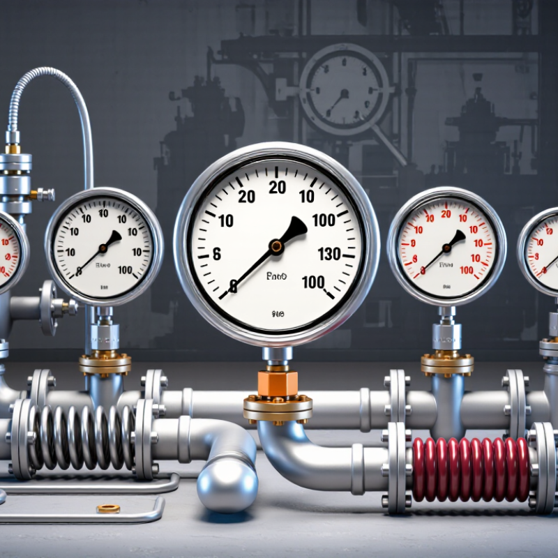
When selecting a pressure gauge, define the measurement task before comparing instruments. A gauge reading is useful only when its range matches the process. Record normal, minimum, and maximum pressure, then allow room for startup surges. A practical target keeps normal pressure near the middle third of the scale. Too narrow a range may damage the mechanism. Too wide a range can hide small changes. I have seen operators choose a gauge by pipe size alone. That shortcut caused confusing readings.
Identify the measured medium, temperature, and pressure type. Is the system using gauge, absolute, or differential pressure? Corrosive fluids, steam, and dirty liquids may require isolated sensing parts or protective accessories. Note pulsation and vibration as well. A steady laboratory line behaves differently from a pump discharge line. The connection location also matters. A gauge installed far from the sensing point may show delayed or distorted pressure. This detail is easy to miss. Field conditions matter.
Define the required accuracy according to the decision being made. Monitoring a filter may need less precision than verifying a calibrated test process. Specify units, dial readability, connection orientation, materials, and environmental exposure. Consider dust, moisture, outdoor temperatures, and accidental impact. Calibration records and traceable testing support dependable readings. Still, specifications can be overly optimistic. Recheck them against real operating conditions, maintenance habits, and the person reading the dial. A clear requirement is often more valuable than a sophisticated gauge.
Choosing the right pressure gauge begins with the process, not the dial size. Identify the measured media, operating pressure, temperature, and expected fluctuations. A gauge should normally operate near the middle of its range. Constant operation at the maximum reading can shorten its service life.
Bourdon tube gauges suit many general industrial applications, including air, water, and hydraulic systems. They are practical and widely used. For corrosive liquids or gases, a diaphragm gauge may provide better separation from sensitive internal parts. Capsule gauges can measure low pressures more effectively, such as gentle gas flows or ventilation systems. Differential pressure gauges are useful when monitoring filters, pumps, or flow restrictions.
The environment changes the decision. Vibration may require a liquid-filled case, while high temperatures may need a remote connection or cooling element. If the media could clog the pressure port, a diaphragm seal can help. Sanitary processes often require smooth, cleanable connections and suitable materials.
I have seen gauges selected by connection size alone. That approach often fails. A readable dial is not enough. Check material compatibility and accuracy requirements with the process engineer. Calibration should match the risk of error, especially near safety limits. I still treat range selection carefully, because real systems rarely behave as neatly as specifications suggest. Record pulsation, pressure spikes, and installation position before ordering. Small details matter.
Selecting the correct pressure range is the first practical decision. A gauge should not operate continuously at its maximum value. In many installations, normal pressure should sit near the middle of the scale. This leaves room for pressure spikes and improves readability. A 0–100 psi gauge may suit a system running at 45 psi better than a 0–60 psi gauge. Stay within the middle. I have seen operators choose a narrow range for sharper readings, then damage the gauge during startup.
Accuracy must match the measurement task. A high-accuracy gauge is valuable for testing, calibration, and process control. It may be unnecessary for a simple pump outlet check. Check the stated accuracy percentage and confirm whether it applies to the full scale or the reading. That difference can be significant. For example, 1% of a 100 psi full scale allows a possible error of 1 psi. Temperature changes, vibration, and pulsation can increase uncertainty.
Review the pressure medium and connection location before ordering. Corrosive fluids may require compatible wetted materials, while pulsating lines may need a damping device. Install the gauge where the dial is easy to read and service. Calibration records should be traceable and recent. Small details matter. No selection is perfect, and I still recheck the expected operating range after installation. Field conditions often reveal assumptions that looked reasonable on paper.
How to Choose the Right Pressure Gauges?
Check Materials, Connections, and Environmental Resistance
Material selection begins with the process fluid, not the gauge price. Stainless steel wetted parts suit many corrosive or hygienic services. However, chloride-rich environments may still cause pitting. Confirm compatibility with the fluid, concentration, temperature, and cleaning chemicals. For oxygen service, use components specifically prepared for oxygen systems. Small details matter.
Connection design also affects reliability. Match thread size, standard, sealing method, and installation direction before ordering. A mismatched thread can leak or damage the process port. ASME B40.100-2022 recommends selecting a range that keeps normal readings near the dial’s middle area. This improves readability and reduces mechanical stress during pressure changes. For pulsating lines, a restrictor or dampening device may help. I have seen gauges fail early because vibration was treated as a minor issue.
Environmental resistance deserves equal attention. IEC 60529 defines IP67 as dust-tight protection and temporary immersion up to one metre. That rating does not prove chemical resistance or suitability for constant underwater use. Check temperature limits, ultraviolet exposure, condensation, and washdown frequency separately. A sealed case may protect the movement, but it cannot correct an incompatible sensing element. In practice, selection often involves trade-offs. The most rugged option is not always the most accurate. Calibration records, material certificates, and service history provide stronger evidence than appearance alone.
How to Choose the Right Pressure Gauges?
A suitable pressure gauge begins with a verified installation plan. Check the process connection, pressure range, temperature exposure, and mounting position. The gauge should remain visible without forcing operators to reach across hot pipes or moving equipment. Mount it upright when specified, and use a suitable seal without blocking the pressure port. Keep vibration low.
Calibration needs deserve equal attention. Ask whether the gauge requires factory calibration, field verification, or both. A qualified technician should compare readings with a traceable reference under controlled conditions. Test several points across the operating range, not only the normal reading. Record the date, reference equipment, ambient temperature, and observed error. Even a small offset can affect process decisions.
Maintenance planning often reveals the best gauge choice. Inspect the lens, pointer movement, connection, and case for corrosion or physical damage. Look for sudden zero shifts after pressure changes. Compare current readings with historical records. If a gauge repeatedly drifts, recalibration may only delay replacement. I have seen maintenance teams overlook blocked impulse lines, which made a sound gauge appear faulty. That mistake is easy to repeat. Define inspection intervals based on service severity, vibration, contamination, and safety impact. Keep clear records, though records are sometimes incomplete. That weakness should be corrected before the next verification cycle.
Use the operating pressure, process medium, temperature, pressure behavior, accuracy requirement, and service environment to select and maintain a suitable pressure gauge.
| Application or Condition | Recommended Gauge Type | Pressure-Range Selection | Installation Requirements | Accuracy and Calibration | Maintenance and Verification | Selection Check |
|---|---|---|---|---|---|---|
| General liquid or gas service | Bourdon-tube gauge | Select a full-scale range so normal operating pressure is approximately 25%–75% of full scale. | Install where the dial is visible. Use a shut-off valve or gauge valve to allow safe isolation and removal. | Common industrial accuracy classes include approximately ±1.0% or ±0.5% of full scale. Calibrate at commissioning and at an interval based on risk and history. | Inspect the case, window, pointer, dial, connection, and leakage condition. Compare periodically with a traceable reference. | Suitable for stable, non-corrosive service |
| Pressure with pulsation or vibration | Liquid-filled gauge or gauge with a pulsation dampener | Keep normal pressure within the middle portion of the scale and avoid continuous operation near full scale. | Use a snubber, restrictor, or dampener where rapid cycling may damage the sensing element. Provide mechanical support for vibrating pipework. | Check zero return and pointer stability after installation. Shorten the calibration interval if cycling causes measurable drift. | Look for foaming, discoloration, leakage, loose fittings, and abnormal pointer movement. Replace damaged dampening components. | Recommended for cycling or vibrating systems |
| Steam or high-temperature process | Bourdon-tube gauge with a siphon or cooling element | Choose a range that keeps normal pressure near the center of the dial while allowing for start-up and upset conditions. | Install a properly filled siphon before commissioning. Confirm that the gauge temperature rating is compatible with the process. | Calibrate after the installation has reached normal operating conditions if temperature can affect the reading. | Verify that the siphon remains filled and is not blocked. Isolate and cool the system before removing the gauge. | Required where process temperature exceeds gauge limits |
| Corrosive, viscous, or contaminated medium | Diaphragm-sealed gauge or gauge with compatible wetted materials | Size the range for the actual process pressure and consider the effect of seal fill fluid and temperature. | Use wetted materials compatible with the medium. Avoid dead legs and install flushing connections where deposits are expected. | Check calibration with the seal system installed; do not expose the sensing diaphragm to incompatible cleaning chemicals. | Inspect the diaphragm seal, capillary, flushing ports, and process connection for corrosion, blockage, or leakage. | Preferred for difficult or chemically aggressive media |
| Low-pressure measurement or differential pressure | Diaphragm, capsule, or differential-pressure gauge | Use the lowest practical full-scale range that covers the maximum permissible operating pressure without over-ranging. | Connect high- and low-pressure ports correctly. Protect low-pressure instruments from static pressure and excessive differential pressure. | Zero-check both ports at equal pressure where applicable. Calibrate at several points across the working range. | Check impulse lines for blockage, condensation, air pockets, and unequal liquid head. Verify both isolation valves and equalizing valves. | Suitable when differential pressure is the measured variable |
| Oxygen or other oxidizing service | Gauge specifically cleaned and prepared for the service | Select a range that avoids frequent operation near the upper limit and accommodates expected pressure transients. | Use service-compatible fittings and ensure all components are free from oil, grease, and other contaminants. Follow applicable oxygen-service procedures. | Use a calibration method and reference instrument approved for the service. Preserve cleanliness after calibration. | Do not use contaminated gauges. Inspect packaging, connection cleanliness, seals, and protective caps before installation. | Requires dedicated cleanliness controls |
| Hazardous or personnel-critical service | Safety-pattern gauge with suitable pressure protection | Choose a range that accommodates normal and abnormal pressure while maintaining readable resolution. | Use a suitable isolation valve, pressure-limiting device, and safe venting arrangement. Position the gauge away from direct exposure to personnel where required. | Set a documented calibration interval according to regulatory, safety, and process requirements. Record as-found and as-left results. | Perform visual checks, leak checks, functional verification, and documented replacement when damage or drift exceeds the permitted tolerance. | Requires formal inspection and records |
| Outdoor, wet, dusty, or corrosive environment | Weather-resistant gauge with suitable enclosure and materials | Allow sufficient range margin for ambient temperature effects and transient pressure conditions. | Use an appropriate mounting position, drain or vent provisions where applicable, and compatible seals. Prevent water from collecting at the connection. | Check for temperature-related zero shift and environmental damage during calibration. | Inspect the window, case, seal, connection, corrosion protection, and mounting hardware. Replace cracked windows or compromised seals. | Suitable when environmental protection is verified |
| Commissioning and initial verification | Gauge selected for the process and verified against a reference | Confirm the scale, pressure unit, connection size, pressure rating, and range before applying pressure. | Check piping cleanliness, correct thread engagement, seal compatibility, orientation, isolation, and leak tightness. Tighten using the connection flats, not the case. | Record the serial or asset identifier, reference standard, test points, environmental conditions, and results. | Establish a baseline zero reading and compare the gauge at several pressure points before placing it into service. | Required before operational acceptance |
| Routine calibration planning | Existing gauge assessed according to service criticality | Review whether the installed range still matches current operating pressure and process changes. | Isolate, depressurize, and make the gauge safe before removal or testing. Use a suitable test pump and reference standard. | Annual calibration is a common starting point, but the interval should be adjusted using drift history, risk, usage, and applicable requirements. | Trend as-found errors. Shorten the interval after excessive drift; extend it only when documented performance supports the change. | Interval must be risk- and history-based |
Copyright © 2025 · All Rights Reserved · Franchino Mold & Engineering